Industrial equipment for the chemical, pharmaceutical and food sectors.

High-specification industrial equipment for the chemical, petrochemical, pharmaceutical, food and energy sectors.

PRESSURE-EQUIPMENT

Pressure and Atmospheric Reactors

CAISA designs and manufactures industrial reactors for a wide range of chemical, pharmaceutical and food processing applications. Our production capability spans from small laboratory-scale reactors to large process vessels with volumes up to 200 m³ and design pressures up to 40 bar. Each unit is engineered from the client’s specific process requirements, ensuring full compliance with the applicable ASME and AD-MERKBLATTER codes.

CAISA’s engineering department provides complete mechanical design, pressure calculations and regulatory technical documentation. Materials include carbon steel, stainless steels AISI 304, 316 and 316L, duplex steels and special alloys selected according to the corrosion demands of each process. Interior surface finishes are tailored to the application: pickled and passivated for the chemical industry, mirror-polished or electropolished for pharmaceutical and food-grade service.

Manufacturing is carried out entirely in-house by qualified welders certified to EN 287 / ASME IX, with dimensional and weld inspection performed in accordance with the applicable codes. Every reactor undergoes hydrostatic or pneumatic pressure testing prior to delivery, accompanied by a complete manufacturing dossier including material certificates, welding procedures and non-destructive examination records.

Technical Specifications

Design pressureUp to 40 bar
Design temperatureUp to 450 °C
MaterialsCarbon steel, AISI 304/316/316L, duplex
Volume rangeFrom 0.1 m³ to 200 m³
Design codeASME, AD-MERKBLATTER
Surface finishPickled/passivated, mirror-polished, electropolished

Applications

  • Chemical and petrochemical industry
  • Pharmaceutical and biotechnology industry
  • Food and beverage industry
  • Wastewater treatment
  • Power generation and utilities

Certifications

  • ASME
  • AD-MERKBLATTER
PRESSURE-EQUIPMENT

Pressure and Atmospheric Vessels

CAISA manufactures pressure and atmospheric vessels for industrial boilermaking equipment, ranging from small accumulators to large process columns. The product range includes separators, filters, surge dampers, hydraulic accumulators and pressurised storage vessels, all designed in accordance with the ASME and AD-MERKBLATTER codes.

Our manufacturing capability covers a wide range of base materials: carbon steels P265GH and P355NH, austenitic stainless steels AISI 304 and 316, duplex 2205, nickel alloys such as Hastelloy C-276 and Inconel 625, and Grade 2 titanium for particularly corrosive services. Welding procedures follow qualified WPS per EN ISO 15614 or ASME IX, with non-destructive examination (radiography, ultrasonics, liquid penetrant testing) integrated into the quality plan for each project.

Each vessel is delivered with its complete technical dossier: fabrication drawings, material specifications with 3.1 certificates per EN 10204, welding and NDT records, post-weld heat treatment logs where applicable, and a pressure test certificate. CE marking and the ASME U-Stamp are processed through the relevant notified and authorised inspection bodies.

Technical Specifications

Design pressureUp to 60 bar
Design temperatureFrom -40 °C to 400 °C
MaterialsCarbon steel, AISI 304/316, Hastelloy, titanium
Capacity rangeFrom 10 litres to 300 m³
Design codeASME, AD-MERKBLATTER
Pressure testHydrostatic or pneumatic per applicable code

Applications

  • Gas-liquid separators in refinery
  • Steam and hydraulic accumulators
  • Distillation and absorption columns
  • Industrial pressure filters and cyclones
  • Process equipment in utility plants

Certifications

  • ASME
  • AD-MERKBLATTER
STORAGE

Storage Tanks

CAISA manufactures storage tanks and vessels for a wide variety of industrial fluids, from water and utilities to aggressive chemical products, food-grade raw materials and pharmaceutical products. The range covers vertical and horizontal tanks from small volumes to large field-erected vessels of thousands of litres, in atmospheric or low-pressure configurations. Structural and wall-thickness design is carried out in accordance with EN 14015 for atmospheric field tanks and the API code for hydrocarbon storage tanks.

Material selection is adapted to the properties of the stored fluid: carbon steel with or without internal lining for non-corrosive products, stainless steel AISI 304 or 316L for food-grade and pharmaceutical service with hygiene requirements, and duplex steel 2205 for corrosive fluids containing chlorides. Tanks can be equipped with functional elements such as heating or cooling jackets, nozzles and connections per the client’s P&ID, baffles, level indicators, manholes and access platforms.

Internal and external surface treatment is defined according to the service: shot-blasting and food-grade or industrial epoxy coating, chemical pickling and passivation for stainless steel, or rubber or resin lining for particularly aggressive fluids. Each tank is delivered with its complete fabrication documentation and, where applicable, with CE marking and the relevant notified body certificate.

Technical Specifications

CapacityFrom 0.5 m³ to 500 m³
Design pressureAtmospheric or low pressure (up to 3 bar)
Design temperatureFrom -10 °C to 200 °C
MaterialsCarbon steel, AISI 304/316/316L, duplex steel
ConfigurationVertical, horizontal, with or without agitation, jacketed
Design codeEN 14015, API as applicable

Applications

  • Storage of chemicals and solvents
  • Food-grade raw material tanks
  • Demineralised water and utilities storage
  • Day tanks for fuels and industrial oils
  • Process tanks for the pharmaceutical industry

Certifications

  • API
004Thermal fluid boilersManufacture of thermal fluid boilers (thermal oil) for industrial processes requiring indirect high-temperature heat without high pressure.
STRUCTURES

Industrial Chimneys

CAISA manufactures industrial flue gas exhaust chimneys for combustion installations and high-temperature processes. We design and build self-supporting and guyed chimneys in carbon steel and stainless steel, with or without thermal insulation, tailored to the specific requirements of each process and to current environmental regulations.

Our equipment covers diameters from 200 mm to 3,000 mm and heights up to 60 m, capable of handling flue gas temperatures up to 600 °C. Structural design complies with EN 13084-7 for steel chimneys and EN 1090-2 for the execution of steel structures. CE marking ensures conformity with applicable essential safety requirements.

CAISA delivers the complete project: structural and thermal calculations, supply of certified materials, shop fabrication with quality control, transport and on-site assembly. We also carry out inspections, repairs and modifications to existing chimneys to adapt them to new operating conditions or updated regulatory requirements.

Technical Specifications

Diameter200 mm to 3,000 mm
HeightUp to 60 m
Flue gas temperatureUp to 600 °C
MaterialsCarbon steel S235/S355, AISI 304/316
StandardEN 13084-7, EN 1090-2

Applications

  • Chemical industry
  • Thermal power plants
  • Cement plants
  • Ceramic industry
  • Cogeneration

Certifications

  • EN 13084-7
  • EN 1090-2
  • CE Marking
HEAT-TRANSFER

Heat Exchangers and Condensers

CAISA manufactures tubular heat exchangers, condensers and special thermal transfer equipment in accordance with TEMA standards and pressure equipment codes. We design and build shell-and-tube, double-pipe and multi-tube units for pressures up to 40 bar and temperatures up to 450 °C, in a wide range of materials selected according to the process fluid and operating conditions.

Our heat exchangers are built to the ASME code, ensuring compliance for use in demanding industrial applications. We work with carbon steel, stainless steels AISI 304/316, copper and titanium, selecting the optimal material combination for each application based on corrosion resistance and the mechanical requirements of the process.

CAISA handles projects of any scale, from pilot plants to large continuous industrial production units. The service includes thermal and hydraulic calculation, material selection, certified manufacturing, pressure testing and all required technical documentation for commissioning.

Technical Specifications

TypeShell-and-tube, double-pipe, multi-tube
Design pressureUp to 40 bar
Design temperatureUp to 450 °C
MaterialsCarbon steel, AISI 304/316, copper, titanium
StandardTEMA, ASME

Applications

  • Chemical and petrochemical
  • Pharmaceutical
  • Cogeneration
  • Industrial refrigeration
  • Food industry

Certifications

  • ASME
  • TEMA
HEAT-TRANSFER

Heating and Cooling Coils

CAISA manufactures heat-exchange coils for heating, cooling and temperature control in reactors, vessels and process equipment. Coils are designed to the ASME code, with heat-transfer area sizing calculated from the process thermal requirements. Materials are selected according to the heat-transfer fluid and the medium inside the vessel: AISI 316L stainless steel for corrosive environments, copper for low-pressure steam services, or special alloys such as Hastelloy and titanium for aggressive fluids.

The coil geometry — pitch, spiral outside diameter, number of turns and distance to the vessel axis — is optimised to maximise the heat-transfer coefficient and minimise pressure drop on the heating/cooling side. CAISA supplies coils for internal installation in new equipment as well as for replacement or surface extension in existing vessels. Connections to the vessel shell are made via certified flanges or threaded fittings, depending on pressure and accessibility requirements.

Each coil is delivered with material certificates, welding procedures and a leak test at design pressure. The technical dossier includes the verification thermal calculation, fabrication drawings and regulatory documentation where applicable, facilitating integration into the technical file of the main vessel.

Technical Specifications

Pipe diameterDN 15 to DN 100
MaterialAISI 304/316L, copper, Hastelloy, titanium
Design pressureUp to 25 bar
Design temperatureFrom -20 °C to 300 °C
Heat transfer areaAs per process calculation
Design codeASME

Applications

  • Heating and cooling of reactors
  • Mixing and agitation vessels
  • Industrial crystallisers
  • Anaerobic digesters
  • Fermentation processes

Certifications

  • ASME
008Equipment repair and modificationRepair and modification of reactors, heat exchangers and pressure vessels in workshop and on-site, with NDT, WPS/PQR and technical reports.
STRUCTURES

Metal Structures (Walkways, Handrails, Stairs)

CAISA fabricates industrial metal structures with EN 1090-2 certification up to execution class IV, covering walkways, stairs, equipment supports and industrial building frameworks. We work with certified materials — S235, S275, S355 and stainless steels — maintaining full documentary quality control at every stage of production.

Our in-house cutting, forming and welding capabilities allow us to manage the entire manufacturing process without subcontracting critical operations. This translates into complete traceability and controlled lead times, even for urgent orders or complex geometries.

CE Marking on our structures confirms compliance with European regulations and simplifies integration into projects subject to site inspection. We offer hot-dip galvanising, industrial painting and stainless steel finishes to match the durability and environmental requirements of each installation.

Technical Specifications

Execution classUp to class IV EN 1090-2
MaterialsS235, S275, S355, stainless steel
FinishesHot-dip galvanised, painted, stainless
StandardsEN 1090-1, EN 1090-2, CTE DB-SE-A

Applications

  • Platforms and walkways
  • Stairs and handrails
  • Equipment supports and skids
  • Industrial building structures
  • Guards and enclosures

Certifications

  • EN 1090-2 up to class IV
  • CE Marking
010Custom metalwork to specification and drawingsFabrication of special metal constructions from client drawings or specifications. One-off parts, prototypes and bespoke industrial solutions.
011Turnkey assemblies and installationsTurnkey industrial assemblies and installations: engineering, fabrication, transport, assembly and commissioning under single-point responsibility.
SPECIAL-PRODUCTS

CLAV System — Sludge Drying

CLAV technology is an indirect thermal low-speed drying system designed for the continuous thermal dewatering of wet sludge. Its purpose is to reduce the final mass sent to landfill by minimising —and when necessary eliminating— leachate generation, thereby cutting residue disposal costs.

The system was originally developed for physico-chemical, biological and mixed wastewater treatment sludge, with initial installations in textile, paper, chemical, metallurgical, food, pharmaceutical, tannery, slaughterhouse, waste recovery and municipal WWTP facilities. Over time, the versatility of the system has been proven: it can dry any material susceptible to dewatering, from wet sludge to compact paste, which after treatment becomes gravel or powder.

The CLAV thermal dryer reduces initial moisture from 90–65% to below 25%, reaching 2–3% when required by the process. The pressure vessel is certified by the Industrial Safety authorities and calculated according to the AD-MERKBLATTER code for carbon steel St37.2. CAISA is a certified pressure equipment manufacturer; welding procedures and welders are equally certified.

Technical Specifications

ParameterValue
Initial moisture90–65%
Final moisture< 25% (down to 2–3%)
Product temperature95–105°C
Thermal mediumSteam, thermal oil or superheated water
Medium temperatureMax. 170°C
Rotation speed~1 r.p.m.
StandardAD-MERKBLATTER, St37.2

Transport System

The thermal medium —pressurised steam, thermal oil or superheated water— never contacts the product being dried. The medium temperature does not exceed 170°C, keeping the product at 95–105°C. This low operating temperature eliminates atmospheric emissions compared to higher-temperature processes and maximises the use of the medium’s latent enthalpy, resulting in a bounded and predictable energy consumption.

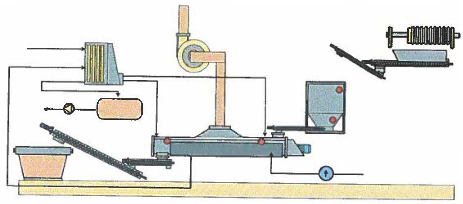
Inside the dryer, a conveyor specially designed for pasty-product transport advances the material through the vessel. The conveyor is dimensioned to guarantee correct product flow as moisture content and rheological properties change along the length of the dryer. The thermal medium circulates through the interior of the transport elements, turning their surfaces into heat-exchange zones; the outer casing also acts as a heat-transfer surface. Low-speed motors (~1 r.p.m., high torque) provide longer thermal exchange time, effective transport force, and low electrical consumption.

A vapour extraction unit captures the moisture vapours generated during dewatering and routes them to a carbon filter or scrubber before atmospheric release, ensuring minimal environmental impact in the dryer area. The entire system is managed by an electrical control cabinet located adjacent to the dryer.
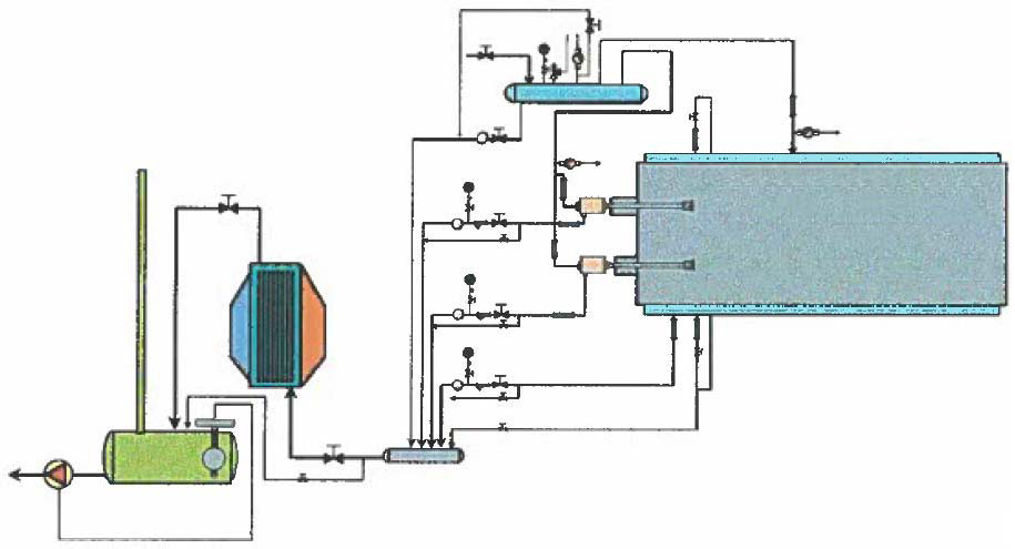
CLAV sludge dryer — general view

CLAV sludge dryer — transport system

Applications

CAISA has installed CLAV systems across multiple industrial sectors:

  • Wastewater treatment: physico-chemical, biological and mixed WWTP sludge; municipal treatment plants
  • Textile and paper industry: process sludge with high organic load
  • Chemical and pharmaceutical: pasty residues requiring controlled low-temperature treatment
  • Food industry: sludge from slaughterhouses, canneries and processing plants
  • Waste management: waste recovery facilities, leachate treatment plants

Standards and Certifications

CLAV drying systems manufactured by CAISA comply with the most demanding standards:

  • AD-MERKBLATTER: German pressure equipment standard used for vessel design (carbon steel St37.2)
  • Certified manufacturer: CAISA holds certification as a Pressure Equipment manufacturer
  • Welding procedures: all welding procedures and welders are duly certified
Technical Specifications

Initial moisture90–65%
Final moisture< 25% (down to 2–3%)
Product temperature95–105°C
Thermal mediumSteam, thermal oil or superheated water
Medium temperatureMax. 170°C
Rotation speed~1 r.p.m.
StandardAD-MERKBLATTER, St37.2

Applications

  • Physico-chemical treatment sludge
  • Biological or mixed WWTP sludge
  • Textile and paper industry
  • Chemical and pharmaceutical industry
  • Food industry and slaughterhouses
  • Waste recovery and municipal WWTP

Certifications

  • Pressure Equipment (AD-MERKBLATTER)
  • Certified welding procedures
SPECIAL-PRODUCTS

Bilge Water Collection System

CAISA has developed a bilge water and grey water collection system designed for port and marina installations. The system operates on a vacuum network: bilge water and grey water are sucked from yachts in a segregated manner. Bilge water is stored in a decanting tank where hydrocarbons are separated from clean water; hydrocarbons go to controlled waste disposal while the clean water is discharged to the public sewer. Grey water is routed directly to the sewage system.

The installation is divided into independent units to provide independent service per zone and to adapt to the phased construction of harbour renovation projects. The dedicated bilge water unit is located with an intake point at the marina fuel station, while grey water units can be configured as independent modules per quay or zone, providing operational flexibility and scalability.

This system was designed and built by CAISA as a turnkey solution for a sports marina undergoing modernisation, demonstrating the company’s capability to develop custom special equipment beyond conventional industrial vessel fabrication.

System Components

CBT — Vacuum and Treatment Centre

The CBT is the core of the bilge water collection system and consists of:

  • Stainless steel decanting tank for bilge water storage and hydrocarbon separation; separated hydrocarbons go to controlled disposal and clean water is discharged to sewage
  • Vacuum pump generating vacuum throughout the closed circuit, mechanically activated when the CRR vacuum valve opens
  • 100-litre stainless steel auxiliary tank with submersible centrifugal pump for discharging separated clean water to sewage
  • Connection accessories, valves and all elements required for correct operation and control
  • Optional: hydrocarbon transfer pump to collection container or transport vehicle for controlled disposal

CRR — Residue Collection Centre

The CRR is the quayside intake point and consists of:

  • Hose reel for hose storage
  • Hose and suction lance
  • VBE (vacuum valve for evacuation)

EBAR — Grey Water Vacuum Unit

One or more EBAR units are installed for grey water collection, each consisting of:

  • Intermediate stainless steel storage tank prior to sewage discharge
  • Vacuum pump generating vacuum in the closed circuit, mechanically activated when any valve in the circuit opens
  • Two centrifugal pumps for pressurised discharge to the public sewer
  • Connection accessories, valves and control elements

Technical Specifications

ParameterValue
Operating principleVacuum network
CBT tankStainless steel
Auxiliary tank100 litres, INOX
PipingHigh-density polyethylene (HDPE)
FixingsPolymer plastic clamps (marine corrosion resistance)
Waste managementHydrocarbons to controlled disposal; clean water to sewage

Applications

This system is specifically designed for port and marina environments:

  • Sports marinas: bilge water collection from leisure yachts and boats
  • Harbours under renovation: phased installation adaptable to progressive construction works
  • Environmental compliance: meeting discharge regulations in port and coastal zones
  • Commercial ports: grey and bilge water collection from smaller vessels

Bilge water collection system schematic

Installation Notes

All intake points connect to CBT or EBAR units via high-density polyethylene (HDPE) piping in various diameters as required. Piping is fixed using polymer plastic clamps to prevent corrosion in the marine environment and is anchored to the quays in the designated space. When necessary, full or partial pipeline installation can be carried out using a pontoon to reach difficult-access areas.

Technical Specifications

Operating principleVacuum network
CBT tankStainless steel
Auxiliary tank100 litres, INOX
PipingHigh-density polyethylene (HDPE)
Waste managementHydrocarbons to controlled waste; water to sewage

Applications

  • Port and marina installations
  • Bilge water collection (yachts and vessels)
  • Segregated grey water collection
  • Sports harbours under renovation

Certifications

  • Certified pressure equipment